BB2B
The BB2B example is inspired by the vehicles invented by Valentino Breitenberg. He created a number of conceptual vehicles which show life-like behaviour. By connecting sensors and motors together in a specific way, different behaviours can be observed.
All code for this is also found in the Roboid Control for Arduino repository as the BB2B example. The first configuration is found in the SwitchesConfiguration.h, the second in the UltraSonicConfiguration.h. Both configurations share the same behaviour as specified in the BB2B.ino code.
Our goal with this example is to make a robot which moves around in a space autonomously, avoiding objects.
How it works
Each wheel will either rotate forward or backward with a fixed speed. When the robot is not colliding, both wheels will rotate forward and thus the robot will move forward.
As both switches are placed at the front of the robot, they will be able to detect whether the robot collides with something. Depending on which switch is closed, the robot will behave as follows:
- Left swich is closed only: the robot will turn right
- Right switch is closed only: the robot will turn left
- Both switches are closed: the robot will drive backward
All of this is achieved by letting the left switch control the right motor and the right switch control the left motor. When the switch is open, the motor rotates forward, when it is closed, the motor rotates backward.
You will see that with this setup, the robot will be able to move around the space quite well.
The code
The example contains a number of different configurations:
- SwitchesConfiguration.h
- UltraSonicConfiguration.h
Each configuration implements the same behaviour, but uses different hardware. In this document we will start with the Switches Configuration and come back to the other configurations at the end.As is common with Roboid Control, the code is split up in a number of sections:
- Hardware setup
- Roboid setup
- Behaviour
Hardware setup
First of all, we use an Arduino Uno to control the roboid. You can change this in the Platform Project Configuration, but keep in mind that when you change the board, you probably also need to change the pins used to connect to the drivers and sensors.
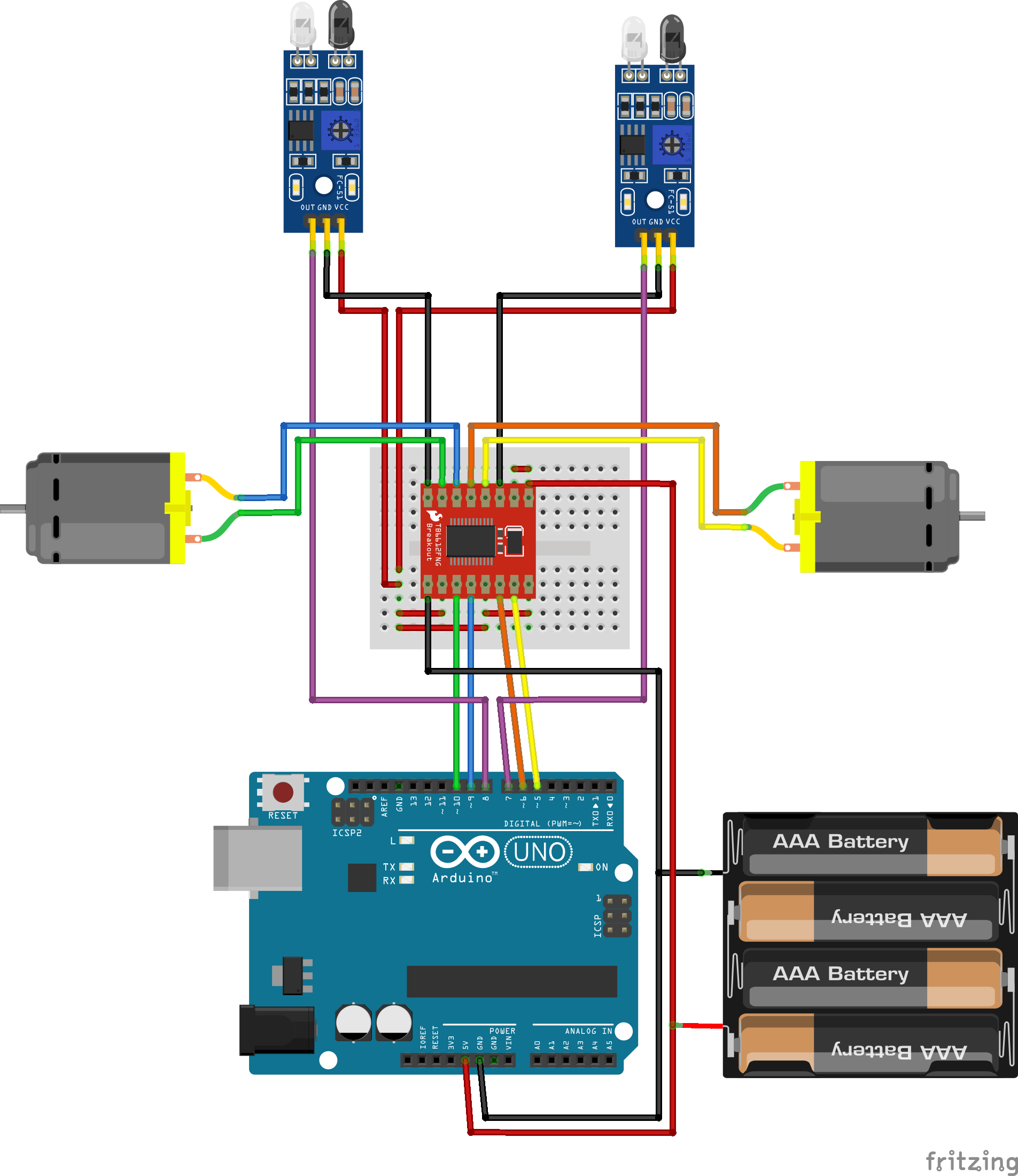
DRV8833
In the Switches Configuration we use a DRV8833 as the motor controller (the picture above shows an TB6612, but it is very similar, see below). This controller has the benefit that the board is small, quite efficient and requires only 4 control wires from the arduino while still providing the possibility to control the motor speed and direction.
In the code, the DRV8833 is setup as follows:
#include "DRV8833.h"
DRV8833 drv8833 = DRV8833(6,  // pinAIn1, Orange wire
                          5,  // pinAIn2, Yellow wire
                          9,  // pinBIn1, Blue wire
                          10  // pinBIn2, Green wire
);
So we only need to specify which 4 pins are used to control the motor controller. When choosing the pin, keep in mind that the pins should support PWM signals.
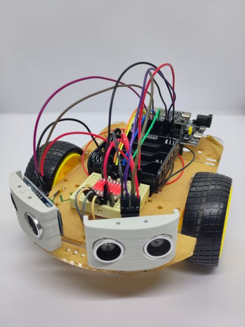
IR proximity sensors
In the Switches Configuration we use IR proximity sensors to detect if the robot is close to a wall. Instead of these sensors, you could use microswitches instead as well. In that case, the robot will need to collide with a wall to change its direction while with the IR sensors, the robot can change its direction when it is nearing a wall.
Note however, that these sensors are sensitive to lighting conditions and the structure and color of the wall and may not give the best results. In general, Time-of-Flight or Ultrasonic sensors give better results. For the use of these latter sensors, see the end of this article.
The IR sensors are basically switches: when an object comes close, a digital pin is pulled low. Therefore we configure these sensors as digital inputs:
#include "Switch.h"
DigitalInput sensorLeft = DigitalInput(8  // Out, Purple wire
);
DigitalInput sensorRight = DigitalInput(2 // Out, Purple wire
);
Resulting code for hardware setup
#include "DRV8833.h"
DRV8833 drv8833 = DRV8833(6, // pinAIn1, Orange wire
                          5, // pinAIn2, Yellow wire
                          9, // pinBIn1, Blue wire
                          10 // pinBIn2, Green wire
);

#include "Switch.h"
DigitalInput sensorLeft = DigitalInput(8  // Out, Purple wire
);
DigitalInput sensorRight = DigitalInput(2 // Out, Purple wire
);
Roboid setup
Now we should configure the roboid, placing the sensors and motors.
sensorLeft.position.angle = -35;
sensorRight.position.angle = 35;
Sensor* sensors[] = {&sensorLeft, &sensorRight};
Perception* perception = new Perception(sensors, 2);
For the sensors we only specify the orientation, their position is not important here. We specify their horizontal angle relative to the forward direction: as the angles are specified in a clockwise manner, we have -35 degrees for the left sensor and 35 degrees for the right.
These sensors are then used to setup the perception of the roboid. The perception module is taking care of detecting objects in the environment of the robot.
The motors are used to set up the propulsion of the robot, which takes care of moving the robot around:
DifferentialDrive* propulsion =
    new DifferentialDrive(&drv8833.motorA, &drv8833.motorB);
As we use a differential drive, we create a new DifferentialDrive instance with the two motors connected to the A and B ports of the DRV8833 motor controller: the left motor is connected to port A and the right to port B. Of couse, this setup should match to the connection on the real robot.
Now we can create the Roboid and we are done:
Roboid* roboid = new Roboid(perception, propulsion);Resulting code for Roboid setup
Roboid* RoboidSetup() {
    sensorLeft.position.angle = -35;
    sensorRight.position.angle = 35;
    Sensor* sensors[] = {&sensorLeft, &sensorRight};
    Perception* perception = new Perception(sensors, 2);

    DifferentialDrive* propulsion =
        new DifferentialDrive(&drv8833.motorA, &drv8833.motorB);

    Roboid* roboid = new Roboid(perception, propulsion);
    return roboid;
}
Roboid Behaviour
The behaviour of the robot is specified in the loop function.
We first read the status of the sensors. We do this with perception. This abstracttion level makes it possible to change the sensors for something completely different, like a camera or lidar, while keeping the behaviour the same. So we specify that for object detection on the left, we look -30 degrees forward, while objects on the right can be detected 30 degrees from forward:
bool obstacleLeft = roboid->perception->ObjectNearby(-30);
bool obstacleRight = roboid->perception->ObjectNearby(30);
bool obstacleLeft = roboid->perception->ObjectNearby(-30, 20);
float leftMotorSpeed = obstacleRight ? -1.0F : 1.0F;
float rightMotorSpeed = obstacleLeft ? -1.0F : 1.0F;
DifferentialDrive* diffDrive = (DifferentialDrive*)&roboid->propulsion;
diffDrive->SetTargetSpeeds(leftMotorSpeed, rightMotorSpeed);
Finally, we have to call the Update function of the roboid. This will update the perception and propulsion to make everything work. This function should be given a timestamp in milliseconds, so we use the millis() function for that.
We add a delay of 100 milliseconds to archieve an update rate of 10 Hz (10 updates per second):
roboid->Update(millis());
delay(100);
Resulting code for Roboid Behaviour
void loop() {
    bool obstacleLeft = roboid->perception->ObjectNearby(-30);
    bool obstacleRight = roboid->perception->ObjectNearby(30);

    float leftMotorSpeed = obstacleRight ? -1.0F : 1.0F;
    float rightMotorSpeed = obstacleLeft ? -1.0F : 1.0F;

    DifferentialDrive* diffDrive = (DifferentialDrive*)&roboid->propulsion;
    diffDrive->SetTargetSpeeds(leftMotorSpeed, rightMotorSpeed);

    roboid->Update(millis());
    delay(100);
}
The complete code for this setup can be found in the SwitchesConfiguration.h for the Setup and the BB2B.ino for the behaviour in the BB2B example.Alternative configurations
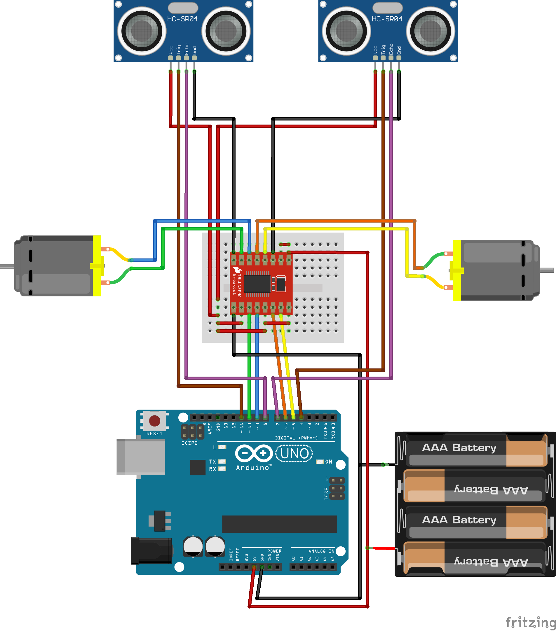
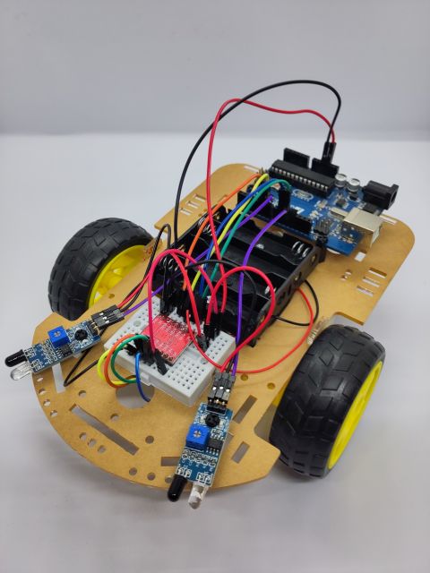
Ultrasonic distance sensors & TB6612 motor controller
To use ultrasonic HC-SR04 sensors, only two changes are necessary. First we need to replace the DigitalInput sensors by UltrasonicSensors:
#include "UltrasonicSensor.h"Then we have to specify at which distance the motors need to reverse. This can be done by setting the triggerDistance of each ultrasonic sensor. The default distance is 1 meter, but here we want to set it to 30 centimeters:
UltrasonicSensor sensorLeft = UltrasonicSensor(11, // pinTrigger, Brown wire
8 // pinEcho, Purple wire
);
UltrasonicSensor sensorRight = UltrasonicSensor(4, // pinTrigger, Brown wire
7 // pinEcho, Purple wire
);
sensorLeft.position.angle = -30;
sensorLeft.triggerDistance = 0.3F;
sensorRight.position.angle = 30;
sensorRight.triggerDistance = 0.3F;

Placement sensors[] = {&sensorLeft, &sensorRight};
Perception *perception = new Perception(sensors, 2);
Next, we replace the DRV883 with a TB6612 motor controller. As this has all the pins of the DRV8833 and we don't want to control the speed of the motors, we can use the same setup.
#include "TB6612.h"
TB6612 tb6612 = TB6612(6,  // pinAIn1, Orange wire
                       5,  // pinAIn2, Yellow wire
                       9,  // pinBIn1, Blue wire
                       10, // pinBIn2, Green wire
The only thing we need to ensure that the PWMA and PWMB pins are pulled high to ensure that the motors are running at full speed: